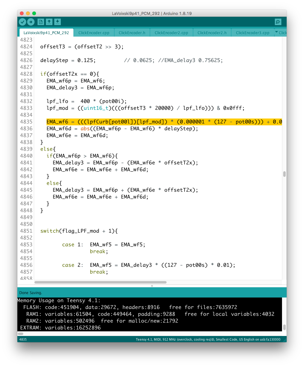
From the video I uploaded earlier, the CombFilter was much less effective as a result of the modifications on the LPF. The result is as follows: *The big noise on the right channel occurred from the mobile phone, by unknown reason. I determined that the cause was a mismatch in the range set for the
A major error of “mishandling of global variables” placed in the LPF
A major error of “mishandling of global variables” placed in the LPF was discovered and corrected in the relevant section. The variable that buffers the audio in the code that builds the LPF was shared among the outputs of Wavetable, resulting in a near-monaural sound output configuration, but the problem was solved by adding a
A function to check various settings for each SceneMemory
is implemented in mode2 = page# 9.
Adding “Depth” to LFO parameters
After adding “Depth” to Modulator’s parameters, I put together the display of parameters related to LFO on one page. I came up with the idea of linking the assignment of the Depth setting parameter in the Modulator to the DelayTimeRange parameter in the 9th item of mode4. The LCD display has Rate/Depth/Feedback in place. The
Adjust the deviation value of the data referenced by the interpolation mechanism of CombFilter.
Adjustments were made to narrow the deviation value of the data referenced by the interpolation mechanism from the delay buffer of the CombFilter. The variable region where the LFO drives is switched according to the delay time setting of the ring buffer that makes up the CombFilter. Calculated 1/8 of the variable region using BitShift
The Feedback loop on the comb filter
The problem that the CombFilter’s Feedback circuit had could be solved by adjusting the level and making a reverse phase connection. After setting the feedback to its maximum value, we checked for points where the audio would break down. Since the Comb Filter operates with 8 x oversampling using Linear Interpolation, the 16-bit data array
LaVoixski@Revisiting the structure of PitchAnt.
I am looking for a structure that will ensure ground potential and continuity with the antenna rods. In this prototype, PogoPin is inserted in the core on the SMA side, while spring pressure ensures a secure contact point, We inserted a cermet of M3 size into the opposite side of the GFRP guyliner, cut a
LaVoixski@Adding a noise filter to PitchDetector
As a result of Eureka! being activated for the first time in a while, it is now possible to avoid the hiccups that used to occur on the Pitch side. In short, a filter that removes unwanted noise components is placed in front of average to prevent intervention, The key is to set the threshold
Chord Sequencer records with free-run status.
The parameter on the left side of the LCD in “THRES” mode, in the center column indicates the starting address of the 16-step chord sequencer. The timing of the trigger signal to drive the steps is set by the threshold point = volume value of the left hand position. This is a recording of the
Access to the parameter of the Chord Sequencer
A function to set the starting address of the Chord Sequencer was implemented on the wireless remote control. As a result of changes to the program that spilled over to the main unit side, the amount of work was greater than expected. In order to execute a circular code with the end of the address