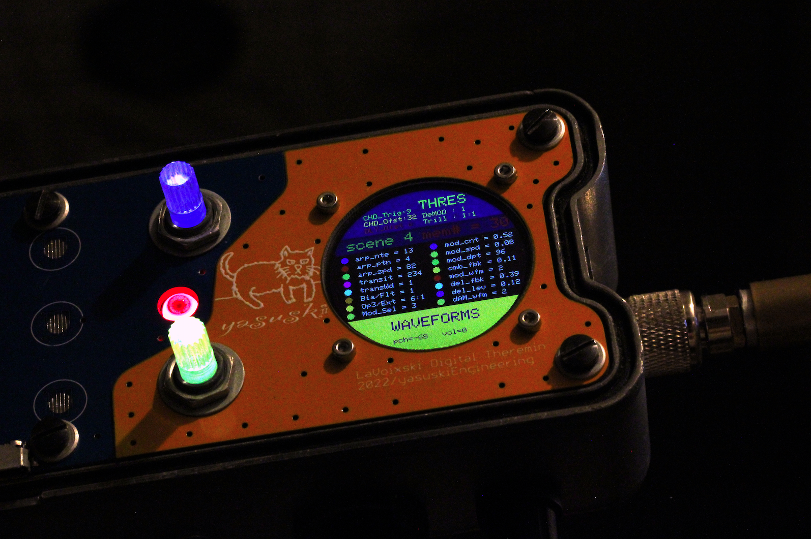
The i2c is received by ESP32S3, and the output is output to the main body of the instrument via ESP-NOW. An illuminated push-switch was installed, but it took a lot of time and effort to drill the holes in the stainless steel. The touch sensor and its control board will be mounted bare on the
Organizing the Confusing Signal System
Due to a failure in naming the delay lines and the group of registers placed in Looper, the rewiring of the signal paths in the delay system could not be done smoothly. To resolve the confusion, I should first clear up the correlation by rearranging the register names. However, the rewriting process must be done
Reassigning the delay line outputs
When the theremin delay signal that had been allocated to outputs #1/2ch is changed to outputs #3/4ch, the separation and intelligibility of the sound image are dramatically improved, and the Transition becomes more effective. Similarly, the Looper’s Delay signal, which had been allocated to #3/4ch, is distributed to #1/2ch. The results are generally good, but
LPF/CombFilter recordings with deep modulation applied.
LPF/CombFilter recordings with deep modulation applied. The Cut Off Frequency of the LPF in the feedback circuit of the CombFilter and the mixing level of the effect were optimized. Perhaps due to the interpolation circuit, the balance setting of 1:1 between the original sound and CombFilter seemed less effective, so the ratio was initially set
Adjusted parameter handling to make CombFilter adjustments smoother
Adjusted parameter handling to make CombFilter adjustments smoother.
Getting the more sweeping range on the combfilter
From the video I uploaded earlier, the CombFilter was much less effective as a result of the modifications on the LPF. The result is as follows: *The big noise on the right channel occurred from the mobile phone, by unknown reason. I determined that the cause was a mismatch in the range set for the
A major error of “mishandling of global variables” placed in the LPF
A major error of “mishandling of global variables” placed in the LPF was discovered and corrected in the relevant section. The variable that buffers the audio in the code that builds the LPF was shared among the outputs of Wavetable, resulting in a near-monaural sound output configuration, but the problem was solved by adding a
A function to check various settings for each SceneMemory
is implemented in mode2 = page# 9.
Adding “Depth” to LFO parameters
After adding “Depth” to Modulator’s parameters, I put together the display of parameters related to LFO on one page. I came up with the idea of linking the assignment of the Depth setting parameter in the Modulator to the DelayTimeRange parameter in the 9th item of mode4. The LCD display has Rate/Depth/Feedback in place. The