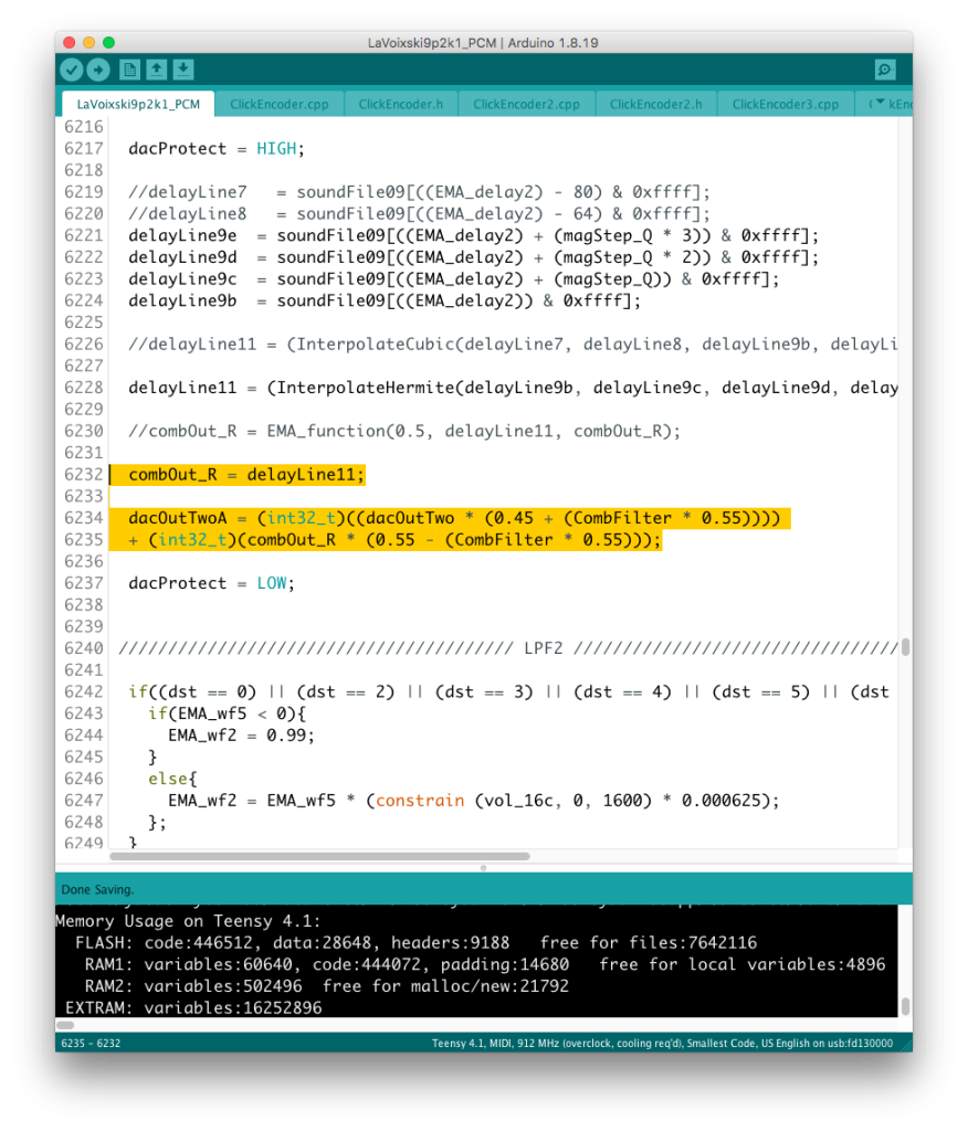
The problem that the CombFilter’s Feedback circuit had could be solved by adjusting the level and making a reverse phase connection.
After setting the feedback to its maximum value, we checked for points where the audio would break down.
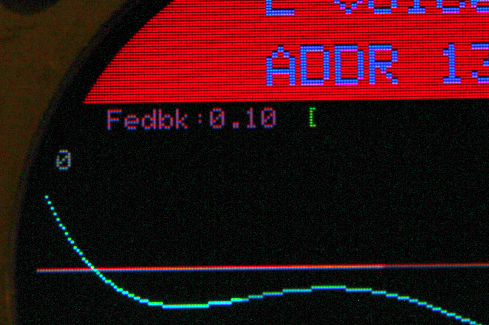
Since the Comb Filter operates with 8 x oversampling using Linear Interpolation, the 16-bit data array reserved as the delay element is actually 13 bits = 8192 steps. Feedback at the time of shooting was set to the maximum value in order to search for the point at which breakdowns occur.
In areas where resonance is strong, the signal will “snap” at the over level, but the parameter settings are designed to cover this to some extent by usage. It is around the mid-level of the resonance frequency that the signal goes dead, and from there the output becomes questionable. In actual operation, the Feedback value should be set just before the overflow occurs.
In any case, there is no change in the strange behavior, and I have a strong feeling that I am doing something stupid around the delay loop. However, there is a possibility that the compiler may have misinterpreted the pattern.
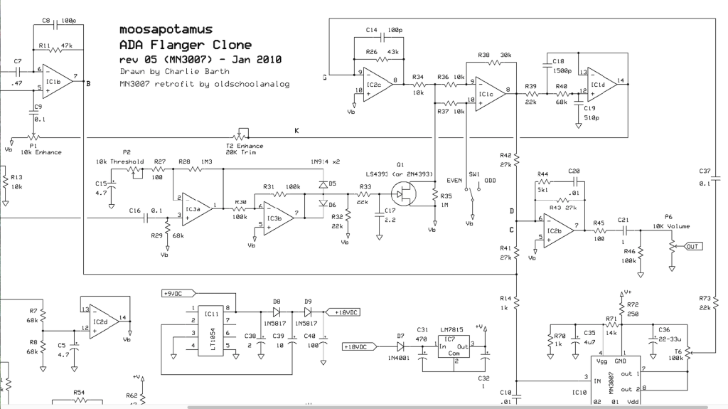
Now, referring to the ADA analog flanger schematic, it seems that the signal to be fed back is filtered and connected in the reverse phase.
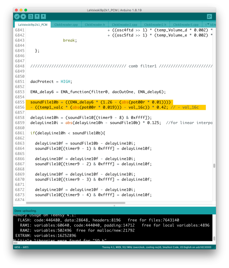
So, I tried applying a simple EMA filter to temp1_valc / temp2_valc,
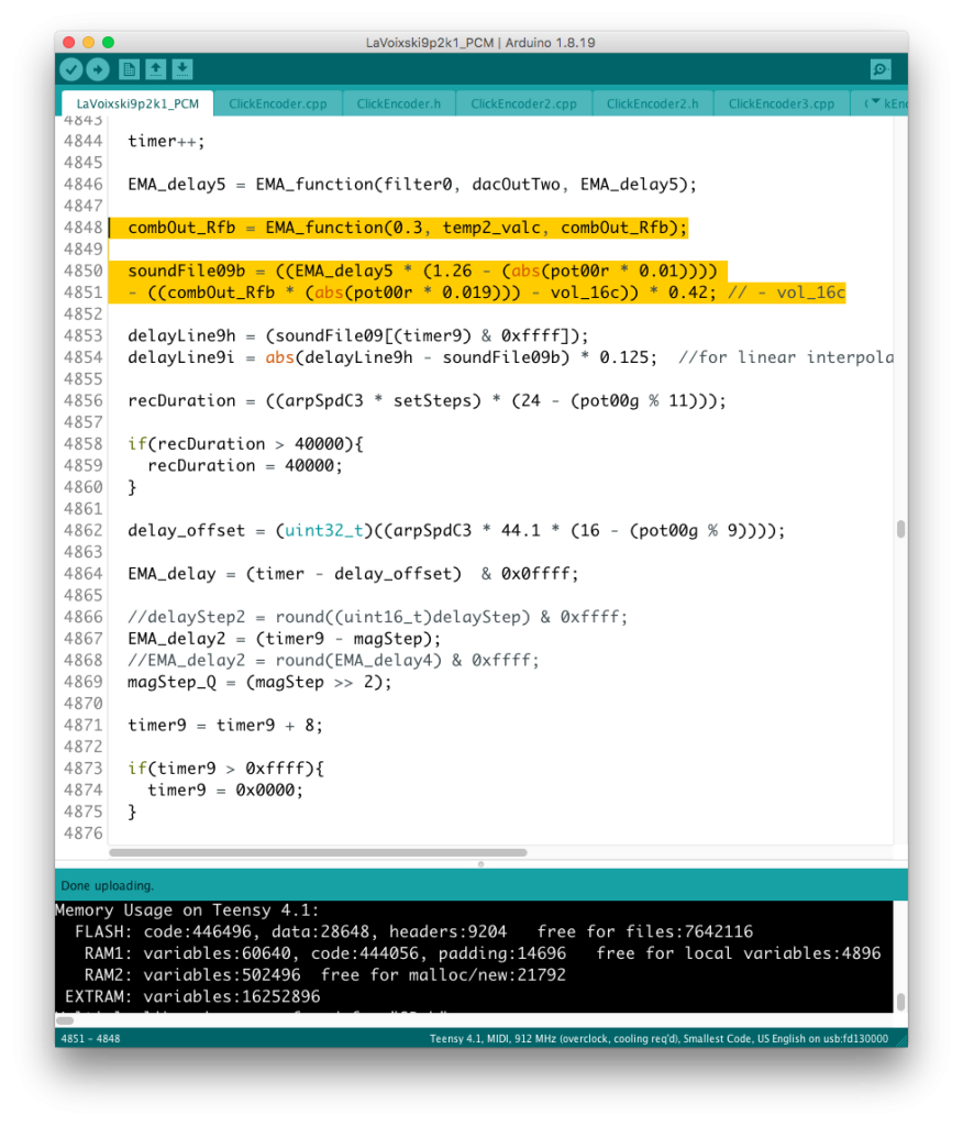
It seems that the effect is indeed more effective, while the over levels are also suppressed to some extent.